
Hydronic PVT Collector for Geothermal Heat Pump Systems
Roof-integrated photovoltaic thermal collector designed for brine loops, borehole regeneration, and low-temperature hydronic systems.
What This Product Is Designed For
Designed for:
Our PVT collectors combine two key renewable-energy technologies in a single, intelligent system: photovoltaics for power generation and solar thermal for heat.
The result is a particularly efficient, space-saving solution that maximizes energy yield on minimal area—ideal for modern buildings with the highest standards of sustainability and cost-effectiveness.
- Ground source heat pumps
- Borehole regeneration
- Brine loop optimization
- Low-temperature heating
- Seasonal thermal storage
- Swimming Pool Heating
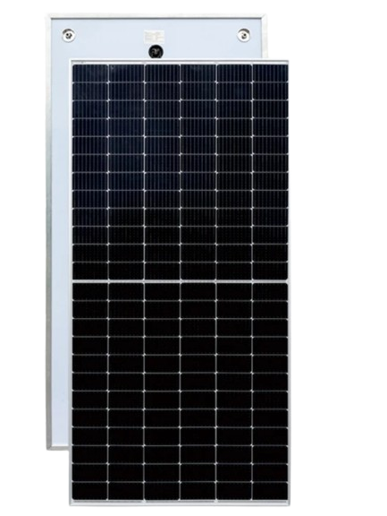
System Application Diagram
Why This Design?
Insulated Rear Structure
Reduces rear-side heat loss and improves thermal retention under low-temperature operating conditions.
Serpentine Heat Exchanger
Provides stable thermal transfer and uniform fluid distribution.
Optimized for Brine Applications
Designed for geothermal and low-temperature hydronic systems.
Photovoltaic Characteristics
| Parameter | Symbol | SW450 | SW580 | SW670 | Unit |
|---|---|---|---|---|---|
| Output at STC | |||||
| Nominal power | Pmax | 450 | 580 | 670 | W |
| Output power tolerance | ΔP | 0 ~ +3 | 0 ~ +3 | 0 ~ +5 | W |
| Module efficiency | ηel | 22.05 | 22.45 | 21.57 | % |
Voltage & Current
| Rated voltage (Vmpp) | Vmpp | 33.06 | 42.87 | 38.20 | V |
| Rated current (Impp) | Impp | 13.61 | 13.53 | 17.55 | A |
| Open-circuit voltage | Voc | 39.73 ± 3% | 51.43 ± 3% | 46.10 | V |
| Short-circuit current | Isc | 14.22 ± 4% | 14.30 ± 3% | 18.62 | A |
Temperature Coefficients
| Voltage (Voc) | β | −0.26 | −0.285 | −0.340 | %/°C |
| Current (Isc) | α | +0.046 | +0.045 | −0.250 | %/°C |
| Power (Pmax) | γ | −0.310 | −0.350 | +0.040 | %/°C |
Thermal Characteristics
| Parameter | Symbol | SW450 | SW580 | SW670 | Unit |
|---|---|---|---|---|---|
| Output | |||||
| Thermal power output | Q̇th | 1210 | 1397 | 1676 | W |
| EN ISO 9806 Collector Coefficients (insulated, with glazing) | |||||
| Optical efficiency | η₀ / a₀ | 58.2 | 58.2 | 58.2 | % |
| First-order heat loss coefficient | a₁ | 10.8 | 10.8 | 10.8 | W/(m²·K) |
| Second-order heat loss coefficient | a₂ | 0 | 0 | 0 | W/(m²·K²) |
| Stagnation temperature | Tstag | 75.6 | 75.6 | 75.6 | °C |
| Operating temperature range | Top | −40 ~ +85 | −40 ~ +85 | −40 ~ +85 | °C |
EN 9806:2017 — wind u = 0 m/s, G = 1000 W/m²
Test conditions: Thermal coefficients (a₀, a₁, a₂) are derived from EN 9806:2017 certification tests for solar collectors without glazing, carried out by KIWA under wind speed u = 1 m/s. The adapted coefficients use: a₀ = η₀ − c₈·u′; a₁ = c₁ + c₃·u′; u′ = u − 3. Thermal power calculated at wind u = 0 m/s, ΔT = 0, G = 1000 W/m².
Context for heat pump integration: These coefficients are characterised for the insulated configuration. The relatively low a₁ (10.8 W/m²·K) compared to an uncovered collector means this panel holds heat well across a wide temperature range — suitable both for domestic hot water pre-heating (higher fluid temperatures, 40–60 °C) and for brine heat pump source operation (0–15 °C fluid). The collector continues to contribute thermal energy to the circuit below ambient temperature, drawing energy from the surrounding air, which is the core mechanism for heat pump source applications.
Hydraulic Parameters
| Parameter | Symbol | SW450 | SW580 | SW670 | Unit |
|---|---|---|---|---|---|
| Heat exchanger area | Ahx | 2.17 | 2.54 | 3.08 | m² |
| Heat exchanger volume | Vhx | 1.0 | 1.1 | 1.3 | L |
| Max. operating pressure | pmax | 0.8 | 0.8 | 0.8 | MPa |
| Recommended flow rate | ṁ | 0.4 | 0.4 | 0.8 | L/s |
| Hydraulic inlet / outlet | — | DN 15 | DN 15 | DN 15 | — |
Flow rate context: 0.4 L/s per module (SW450/580) equates to 1440 L/h. This is the manufacturer’s recommended rate for full thermal output. For brine heat pump source applications where lower fluid temperatures are used, reduced flow rates (down to ~30–40% of rated) are common practice and reduce pumping energy without significant penalty to annual thermal yield. Confirm flow rate with your system design before pump selection.
Thermal Output by Application
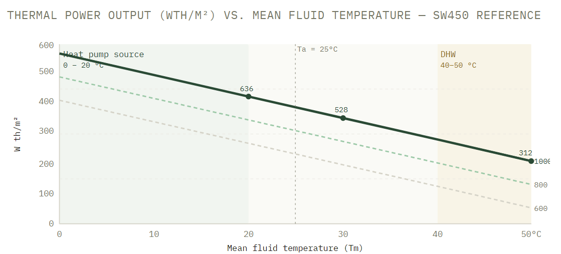
Thermal power output (Wth/m²) vs. mean fluid temperature — SW450 reference
Performance derived from a₀, a₁ (wind u=1 m/s) · STC: T=25°C, G=1000 W/m²
Reference values (G = 1000 W/m², Ta = 25 °C) from datasheet: 636 Wth/m² at 20 °C · 528 Wth/m² at 30 °C · 312 Wth/m² at 50 °C. The green shaded zone indicates typical brine heat pump source operating range (0–20 °C fluid temperature), where the collector draws heat from both solar irradiation and ambient air. The amber zone indicates domestic hot water pre-heating range.
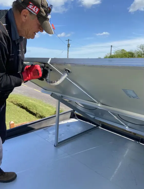
Installation Notes
What installers need to know
Orientation
Portrait or landscape Landscape preferred where parallel hydraulic strings are used
Tilt (heat pump source)
15° – 45° Shallower tilts (15–25°) increase annual thermal yield for HP source duty.
Hydraulic connections
DN 15 (all variants)
Confirm fitting type (thread or compression) on order. Standard BSP or metric adaptors available.
Freeze protection
Propylene or ethylene glycol 30–35% vol. recommended for −15 °C protection. Drain-back not required in active brine circuits.