The Complete Engineering Guide to Performance, Reliability and Certification

Published: March 16, 2026
Last Modified:July 7, 2026

Executive Summary

At a Glance

For engineers and project developers, independent testing is the foundation of reliable PVT system design.

This guide explains how internationally recognized testing standards such as ISO 9806 and EN 12975 evaluate thermal performance, hydraulic characteristics, structural reliability, environmental durability, and product documentation.

Using verified laboratory evidence—including measured thermal efficiency coefficients, pressure-drop data, and durability evaluations—engineers can compare products objectively, optimize heat pump integration, and reduce technical uncertainty during specification and procurement.

Whether selecting a collector, reviewing a test report, or designing a renewable heating system, understanding the engineering meaning behind laboratory data is essential for informed decision-making.

Choosing a photovoltaic-thermal (PVT) collector involves far more than comparing peak efficiency values on a datasheet. For engineers, consultants, and project developers, long-term performance depends on verified thermal output, hydraulic behavior, structural integrity, environmental durability, and compliance with internationally recognized testing standards.

A comprehensive test report demonstrates how a collector performs under controlled laboratory conditions and how it responds to mechanical loads, temperature cycling, pressure, weather exposure, and decades of expected operation. These measured results provide objective evidence that supports engineering calculations, equipment selection, and project risk assessment.

This guide explains the complete testing framework used for liquid-based PVT collectors, including thermal performance, hydraulic characteristics, durability evaluation, safety verification, and certification requirements. It also shows how engineers can interpret laboratory reports and distinguish independently verified performance from marketing claims.

Throughout this guide, examples are drawn from independently tested liquid PVT collectors evaluated in accordance with ISO 9806:2017 and EN 12975:2022, together with measured laboratory results where applicable. The referenced Intertek testing program concluded that the submitted PVT collector family complied with all applicable requirements of both standards.


Why PVT Collector Testing Matters

PVT collectors combine photovoltaic electricity generation with solar thermal energy recovery in a single product. Because they simultaneously operate as electrical equipment, hydraulic heat exchangers, and exterior building components, they must withstand a wide range of operating conditions throughout their service life.

Unlike conventional PV modules, a liquid PVT collector must demonstrate not only electrical reliability but also:

  • Stable thermal efficiency
  • Hydraulic integrity under pressure
  • Resistance to repeated thermal expansion and contraction
  • Mechanical resistance to wind and snow loads
  • Protection against rain penetration
  • Long-term weather durability
  • Safe operation at stagnation temperature
  • Reliable installation documentation

Each of these characteristics affects overall system performance, maintenance requirements, and investment risk. Independent laboratory testing provides measurable evidence that these performance characteristics have been verified using standardized procedures rather than estimated through theoretical calculations or manufacturer declarations alone.

For designers integrating PVT collectors with heat pumps, these verified parameters are particularly important because collector efficiency, pressure loss, operating temperature, and structural limits directly influence system sizing, circulating pump selection, seasonal energy yield, and long-term operational reliability.


What Does a Complete PVT Test Report Cover?

International testing standards evaluate a PVT collector through a series of laboratory and outdoor tests rather than a single performance measurement.

A comprehensive report typically includes:

Test CategoryEngineering Purpose
Thermal PerformanceMeasures useful heat output under different operating conditions
Optical EfficiencyDetermines maximum conversion efficiency under standard conditions
Heat Loss CoefficientsQuantifies thermal losses as operating temperature increases
Pressure DropEvaluates hydraulic resistance for pump sizing
Internal PressureVerifies hydraulic safety under elevated operating pressure
Stagnation TemperatureAssesses maximum collector temperature without circulation
Mechanical LoadConfirms resistance to wind and snow loading
Thermal ShockEvaluates resistance to rapid temperature changes
Rain PenetrationVerifies weatherproof construction
Impact ResistanceAssesses glazing durability against impact
Exposure TestingSimulates long-term outdoor operation
Final InspectionConfirms absence of degradation after all testing

The Intertek laboratory program for the referenced PVT collector family included all of these major evaluations, including internal pressure testing, stagnation testing, exposure testing, external and internal thermal shock, rain penetration, mechanical loading, impact resistance, thermal performance testing, pressure-drop measurement, and final inspection.

International Standards Behind PVT Collector Testing

Independent testing is only meaningful when every laboratory evaluates products using the same procedures. International standards provide this common engineering language by defining how collectors are tested, what operating conditions are used, how performance coefficients are calculated, and which acceptance criteria must be satisfied.

For engineers, understanding these standards is just as important as understanding the measured data itself. A thermal efficiency value has little meaning unless it has been determined using a recognized and repeatable test methodology.


The International Testing Framework

Modern liquid-based PVT collectors are typically evaluated using a combination of product standards, testing standards, and certification schemes.

StandardPurposeTypical Use
ISO 9806Test methods for solar thermal collectorsLaboratory testing
EN 12975Product requirements and documentationEuropean compliance
Solar Keymark Scheme RulesThird-party certification frameworkEuropean market certification
IEC 61215PV module reliability qualificationPhotovoltaic module validation
IEC 61730PV electrical safetyElectrical safety
EN 14511Heat pump testing and ratingSystem integration
EN 14825Seasonal heat pump performance (SCOP)System design

Each standard focuses on a different aspect of product quality. Together they establish a comprehensive engineering framework for evaluating safety, durability, thermal performance, electrical reliability, and long-term operation.


ISO 9806: The Core Test Standard for Solar Thermal Collectors

For liquid PVT collectors, ISO 9806:2017 is the primary international standard defining laboratory test methods.

Rather than specifying minimum performance values, ISO 9806 specifies how performance must be measured. Every accredited laboratory following ISO 9806 applies the same procedures, allowing engineers to compare products objectively.

The standard covers several categories of testing:

  • Thermal performance
  • Pressure resistance
  • Stagnation behavior
  • Mechanical loading
  • Thermal shock
  • Rain penetration
  • Weather exposure
  • Impact resistance
  • Hydraulic pressure drop
  • Long-term durability
  • Final inspection

The Intertek report for the Solis PVT collector family explicitly states that testing was conducted according to ISO 9806:2017, covering these major evaluations before concluding compliance.


EN 12975: Product Requirements Beyond Performance

While ISO 9806 focuses on test methods, EN 12975:2022 defines additional product requirements that support safe installation and market acceptance.

These requirements extend beyond laboratory measurements and include:

  • Product labeling
  • Installation documentation
  • Transport instructions
  • Operating limitations
  • Maintenance guidance
  • Maximum operating pressure
  • Maximum operating temperature
  • Recommended installation angles
  • Heat transfer fluid requirements
  • Mechanical load information

These documents are essential for installers, commissioning engineers, and system designers. Even a technically excellent collector may fail to meet market requirements if documentation is incomplete.

The Intertek assessment includes verification of both labeling and installation documentation in accordance with EN 12975:2022, confirming compliance with the standard’s documentation requirements.

ISO9806 vs EN12975

ISO9806EN12975
Test MethodProduct Requirement
Laboratory ProcedureDocumentation
Performance MeasurementProduct Compliance
Thermal TestingInstallation Manual
Pressure DropLabelling

Solar Keymark: Independent European Certification

Many European projects require more than laboratory testing alone. They require third-party certification demonstrating that testing has been independently reviewed and that factory production remains consistent over time.

This role is fulfilled by the Solar Keymark certification scheme.

Solar Keymark combines:

  • Accredited laboratory testing
  • Factory inspection
  • Quality management review
  • Ongoing surveillance
  • Independent certification

Rather than replacing ISO 9806, Solar Keymark builds upon it. Test data generated under ISO 9806 forms one of the technical foundations for certification.

For specifiers, Solar Keymark often simplifies product approval because it provides confidence that declared performance has been independently verified and is supported by continued manufacturing oversight.


Why PVT Collectors Also Depend on PV Standards

A liquid PVT collector is fundamentally different from a conventional solar thermal collector because it integrates photovoltaic technology into the same product.

As a result, engineers should evaluate both:

  • Thermal collector performance
  • Photovoltaic module reliability

The PV component is commonly assessed against standards such as IEC 61215 (reliability qualification) and IEC 61730 (electrical safety), while the thermal collector is assessed using ISO 9806 and related standards.

This dual-standard approach ensures that neither the electrical nor the thermal subsystem is evaluated in isolation.

For the tested Solis PVT collector family, the integrated PV modules referenced in the report had already been approved under TÜV certification before being incorporated into the PVT collector family tested by Intertek.


How Independent Testing Supports Engineering Decisions

A common misconception is that testing exists only to obtain certification.

In practice, engineers rely on laboratory reports throughout the design process because measured parameters directly influence system calculations.

For example:

Engineering DecisionTest Data Used
Collector sizingThermal efficiency coefficients
Pump selectionPressure-drop measurements
Pipe sizingHydraulic characteristics
Expansion vessel designFluid volume
Freeze protectionOperating medium specification
Structural designMechanical load results
Roof suitabilityCollector weight
Safety analysisStagnation temperature
Maintenance planningDurability testing

Without independently measured values, many of these calculations would depend on assumptions rather than verified engineering data.


Laboratory Testing vs. Marketing Claims

Manufacturers frequently advertise:

  • High efficiency
  • Superior durability
  • Excellent reliability
  • Better heat output

These claims may be accurate—or they may simply reflect measurements taken under favorable conditions without standardized verification.

An accredited laboratory report provides a different level of confidence because:

  • Test procedures follow internationally recognized standards.
  • Environmental conditions are controlled and documented.
  • Equipment is calibrated.
  • Measurements are repeatable.
  • Results are independently reviewed.

For engineering projects, this distinction is significant. Procurement decisions based on standardized test data reduce uncertainty and allow competing products to be compared using consistent criteria rather than marketing language.

Thermal Performance Testing: Understanding What the Numbers Really Mean

For most engineers, the thermal performance section is the most valuable part of a PVT collector test report. It contains the measured coefficients used to predict useful heat output under different weather conditions, operating temperatures, and system configurations.

Unlike a single “efficiency” value shown in a brochure, ISO 9806 testing generates a mathematical performance model that allows engineers to estimate collector output across a wide range of real operating conditions.

Understanding these parameters is essential for:

  • Selecting the correct collector area
  • Predicting seasonal energy yield
  • Designing brine-source heat pump systems
  • Comparing different PVT collectors fairly
  • Performing dynamic building simulations

How ISO 9806 Measures Thermal Performance

Thermal performance testing is conducted under carefully controlled outdoor or indoor conditions using standardized instrumentation and procedures defined in ISO 9806:2017.

During testing, the laboratory measures:

  • Solar irradiance
  • Ambient temperature
  • Fluid inlet temperature
  • Fluid outlet temperature
  • Flow rate
  • Wind speed

These measured values are then used to calculate the collector’s useful thermal power and derive standardized performance coefficients.

In the Intertek evaluation, thermal performance testing was carried out using water as the heat-transfer fluid with a specified test flow rate, and performance coefficients were calculated separately for the PVT430 and PVT670 collectors.


Optical Efficiency (η₀)

What Is Optical Efficiency?

Optical efficiency (η₀) represents the maximum theoretical thermal efficiency of a collector when there is virtually no temperature difference between the heat-transfer fluid and the surrounding air.

It answers one simple question:

How effectively can the collector convert incoming solar radiation into useful heat under nearly ideal conditions?

Because thermal losses are minimal at this operating point, η₀ primarily reflects:

  • Glass transmittance
  • Absorber absorptance
  • Optical losses
  • Internal heat transfer between absorber and fluid

It is not the efficiency the collector will achieve throughout the year.


Why η₀ Should Not Be Compared Alone

A common mistake is comparing collectors solely by optical efficiency.

For example:

Collector A

η₀ = 0.84

Collector B

η₀ = 0.81

Many buyers immediately conclude Collector A is better.

In reality, this conclusion may be completely wrong.

If Collector A has much higher thermal losses, its annual energy production may actually be lower than Collector B under typical operating conditions.

Engineers therefore evaluate η₀ together with the heat-loss coefficients rather than as an isolated number.


Measured Optical Efficiency

The Intertek report provides measured peak efficiency values referenced to different collector areas.

For example, the tested PVT670 collector achieved a measured beam optical efficiency (η₀,b) of 0.465 when referenced to the aperture area, with corresponding values also reported using gross and absorber areas. These coefficients are calculated according to ISO 9806 methodology and provide the starting point for the collector performance equation.

Measured Data
Optical efficiency values above are laboratory measurements from the Intertek test report.


Heat Loss Coefficient (a₁)

What Does a₁ Represent?

Even under sunshine, every collector continuously loses heat to the surrounding air.

The a₁ coefficient describes the linear component of this heat loss.

As the collector temperature rises above ambient temperature, thermal losses increase approximately in proportion to that temperature difference.

A lower a₁ generally indicates:

  • Better insulation
  • Reduced convection losses
  • Lower conductive heat transfer
  • Improved collector construction

Why Is a₁ Important?

In low-temperature applications—such as brine-source heat pumps—the operating temperature difference between the collector and ambient air is relatively small.

Consequently, heat losses remain limited, allowing the collector to operate closer to its peak efficiency.

This is one reason why liquid PVT collectors are particularly well suited to low-temperature renewable heating systems.


Measured a₁ Values

The tested collector family shows measured linear heat-loss coefficients in accordance with ISO 9806, with values reported for different reference areas. These coefficients are included in the performance equation used to predict collector output under varying operating conditions.

Measured Data
These coefficients originate from standardized laboratory testing rather than manufacturer estimation.


Heat Loss Coefficient (a₂)

Why Is a Second Heat Loss Coefficient Needed?

Thermal losses do not increase perfectly linearly.

As collector temperature continues to rise, additional effects become significant, including:

  • Radiation losses
  • Non-linear convection
  • Temperature-dependent material behavior

The a₂ coefficient accounts for these higher-order losses.

While its numerical value is usually much smaller than a₁, it becomes increasingly important during:

  • Summer operation
  • High supply temperatures
  • Stagnation conditions
  • Domestic hot water production

Engineering Interpretation

For many heat-pump applications, the influence of a₂ is relatively modest because the collector normally operates at lower temperatures.

However, ignoring a₂ when modeling high-temperature operation can lead to overestimation of useful thermal output.


The Collector Performance Equation

ISO 9806 expresses collector efficiency using a standardized equation that combines optical efficiency with heat-loss coefficients.

Conceptually, the equation states:

Useful Efficiency = Optical Efficiency − Linear Heat Loss − Non-linear Heat Loss

This mathematical model allows engineers to calculate expected thermal output for any combination of:

  • Solar irradiance
  • Ambient temperature
  • Mean fluid temperature

Rather than relying on a single efficiency value, designers can predict collector behavior throughout an entire heating season.


Effective Thermal Capacity (a₅)

Not all incoming solar energy is transferred immediately to the circulating fluid.

Part of the energy is temporarily stored within:

  • The absorber
  • Hydraulic tubes
  • Metal frame
  • Internal components

This stored energy is represented by the effective thermal capacity (a₅).

Collectors with higher thermal capacity respond more slowly to changes in solar radiation but often provide smoother thermal output under variable weather conditions.

The Intertek report includes measured effective thermal capacity values both with and without heat-transfer fluid, providing engineers with additional data for transient system simulations.


Understanding Collector Power Output Curves

One of the most practical sections of an ISO 9806 report is the power-output graph.

Instead of presenting only efficiency, the laboratory calculates the actual useful thermal power delivered by the collector under different operating conditions.

The Intertek report includes calculated power-output curves for multiple irradiance levels (400, 700 and 1000 W/m²), illustrating how useful thermal power decreases as the temperature difference between the collector and ambient air increases. For the tested PVT670 collector, the reported peak thermal power under the defined test conditions reaches 1350 W per collector unit.

These graphs help engineers answer practical questions such as:

  • How much heat will the collector deliver on a cold winter day?
  • How does performance change as the brine temperature rises?
  • What collector area is required to meet the heating demand?
  • Which operating temperature provides the highest seasonal efficiency?

Unlike brochure values, these curves provide a realistic basis for engineering calculations because they are derived from standardized laboratory measurements.


Why Thermal Performance Must Be Interpreted Together

No single coefficient determines whether one PVT collector is “better” than another.

A meaningful engineering comparison always considers the complete performance model, including:

  • Optical efficiency (η₀)
  • Linear heat loss (a₁)
  • Non-linear heat loss (a₂)
  • Effective thermal capacity (a₅)
  • Incidence angle modifier (IAM)
  • Power-output curves
  • Pressure-drop characteristics

Only by evaluating these parameters together can engineers estimate seasonal performance accurately and select the most suitable collector for a specific heat-pump application.

Hydraulic Performance Testing: Why Flow Characteristics Matter as Much as Thermal Efficiency

Thermal performance determines how much solar energy a PVT collector can convert into useful heat. Hydraulic performance determines how effectively that heat can be transported through the system.

In practical engineering, these two aspects are inseparable. A collector with excellent thermal efficiency may still lead to poor system performance if it introduces excessive hydraulic resistance, requires oversized pumps, or creates an unbalanced flow distribution across the collector array.

For this reason, ISO 9806 includes hydraulic testing alongside thermal performance measurements. These tests provide engineers with the information needed to design circulating loops, size pumps, evaluate energy consumption, and optimize the overall efficiency of a heat pump system.


Why Hydraulic Performance Matters

The hydraulic circuit is responsible for transferring thermal energy from the collector to the heat pump, thermal storage tank, or other downstream equipment.

Poor hydraulic design can result in:

  • Higher pumping power
  • Uneven flow distribution
  • Reduced collector efficiency
  • Increased operating costs
  • Greater wear on circulation pumps
  • Lower seasonal system performance

A well-designed collector should therefore achieve a balance between efficient heat transfer and low hydraulic resistance.


What Is Pressure Drop?

Pressure drop is the reduction in fluid pressure as the heat-transfer medium flows through the collector.

Every hydraulic component—including pipes, valves, fittings, heat exchangers, and collectors—creates resistance to flow.

The circulation pump must overcome the combined pressure drop of the entire hydraulic circuit.

Although pressure drop is unavoidable, minimizing unnecessary resistance improves overall system efficiency by reducing auxiliary electricity consumption.


What Causes Pressure Drop?

Several design factors influence the hydraulic resistance of a PVT collector:

  • Tube diameter
  • Internal flow path
  • Length of hydraulic channels
  • Number of bends
  • Surface roughness
  • Flow velocity
  • Fluid viscosity

These characteristics vary between manufacturers, which is why standardized laboratory measurements are essential for objective comparison.


How ISO 9806 Measures Pressure Drop

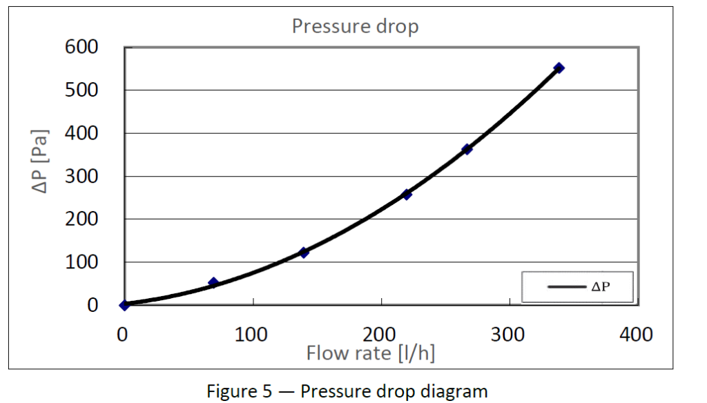
Hydraulic testing measures the pressure difference between the collector inlet and outlet under controlled operating conditions while varying the flow rate.

The resulting data are used to establish a pressure-drop curve showing how hydraulic resistance changes as flow increases.

Unlike thermal efficiency measurements, which depend heavily on solar irradiance and temperature, pressure-drop testing is primarily influenced by the collector’s internal hydraulic design.


Measured Pressure Drop Results

The Intertek laboratory measured the hydraulic pressure loss of the tested PVT collector using water at approximately 20.5°C, recording pressure differences across a range of flow rates.

The report also derives pressure-drop coefficients for engineering calculations:

  • Pressure-drop coefficient a
  • Pressure-drop coefficient b

These coefficients allow designers to estimate pressure loss under different operating flow rates without repeating laboratory testing.

Measured Data
The coefficients and pressure-drop curve are laboratory measurements from the Intertek report.


Why Pressure Drop Influences Pump Selection

The circulation pump must provide sufficient pressure to overcome the resistance of the entire hydraulic circuit while maintaining the required flow rate.

If the collector contributes excessive hydraulic resistance:

  • A larger pump may be required.
  • Electrical consumption increases.
  • Operating costs rise.
  • Seasonal system efficiency decreases.
  • Pump lifetime may be shortened.

Conversely, selecting a collector with unnecessarily low pressure drop is not always advantageous if this compromises heat-transfer effectiveness.

Good engineering design seeks the optimum balance between hydraulic resistance and thermal performance.


Flow Rate: Finding the Engineering Optimum

Flow rate directly affects how heat is transferred from the absorber to the circulating fluid.

If the flow rate is too low:

  • Fluid temperature rises rapidly.
  • Collector operating temperature increases.
  • Thermal losses become larger.
  • Overall efficiency decreases.

If the flow rate is excessively high:

  • Additional pumping energy is required.
  • Hydraulic resistance increases.
  • Incremental heat-transfer improvements become marginal.

The optimum operating point depends on:

  • Collector design
  • Heat pump operating conditions
  • Hydraulic layout
  • Pipe length
  • Climate
  • Control strategy

Standardized Flow Rate Improves Comparability

To ensure meaningful comparisons between products, ISO 9806 specifies standardized testing conditions.

For the tested Solis PVT collector family, the thermal performance evaluation used a defined flow rate per square metre of collector gross area, ensuring that the reported performance coefficients can be compared consistently with other collectors tested under the same methodology.

This standardization is one reason why independently tested products provide a more reliable basis for engineering design than isolated manufacturer measurements performed under unknown conditions.


Why Higher Flow Is Not Always Better

A common misconception is that increasing flow rate always increases useful heat output.

In reality:

  • Higher flow reduces fluid temperature rise.
  • Lower fluid temperature reduces thermal losses.
  • However, pumping power also increases.

Eventually, additional pumping energy outweighs the thermal gains.

For this reason, professional system designers evaluate the entire system, not just collector performance.

The objective is to maximize seasonal system efficiency, rather than maximizing the instantaneous heat output of the collector alone.


Hydraulic Performance and Heat Pump Design

Hydraulic characteristics become particularly important in brine-source heat pump systems.

Unlike conventional solar hot-water systems, PVT collectors supplying a heat pump typically operate at relatively low fluid temperatures and circulate fluid continuously over long periods.

This operating mode places greater emphasis on:

  • Stable hydraulic performance
  • Low pumping energy
  • Consistent flow distribution
  • Reliable long-term operation

Measured pressure-drop data therefore play an important role in:

  • Pump sizing
  • Pipe diameter selection
  • Collector array configuration
  • Parallel versus series connection
  • Seasonal energy modelling

Why Hydraulic Data Should Never Be Ignored

When comparing PVT collectors, buyers often focus exclusively on thermal efficiency values.

However, two collectors with similar thermal performance can behave very differently once installed if their hydraulic characteristics differ significantly.

Ignoring pressure-drop data may lead to:

  • Oversized circulation pumps
  • Higher operating costs
  • Poor hydraulic balancing
  • Reduced seasonal performance
  • Lower return on investment

Professional engineering decisions therefore consider both thermal and hydraulic performance together, rather than evaluating either in isolation.

Mechanical Reliability and Environmental Testing: Proving Long-Term PVT Collector Durability

Thermal performance testing answers an important question:

How much heat can a PVT collector produce?

Hydraulic testing answers another:

How efficiently can that heat be transported?

However, for a renewable energy system expected to operate for decades, engineers must answer a third question:

Can the collector maintain its performance after years of exposure to outdoor conditions?

A PVT collector installed on a roof or ground structure is continuously exposed to:

  • Wind pressure
  • Snow loading
  • Rain
  • Solar radiation
  • Temperature cycling
  • Thermal expansion and contraction
  • Freeze-thaw cycles
  • High stagnation temperatures
  • Mechanical impacts

Therefore, reliability testing is designed to verify that the collector is not only efficient when new, but also structurally and functionally stable throughout its expected lifetime.


Why Durability Testing Is Critical for PVT Collectors

Unlike conventional PV modules, liquid PVT collectors contain additional components:

  • Heat transfer channels
  • Hydraulic connections
  • Absorber plates
  • Thermal insulation layers
  • Sealing structures
  • Fluid-containing circuits

These components introduce additional engineering challenges.

A failure in a PVT collector may result in:

  • Loss of thermal output
  • Fluid leakage
  • Reduced PV cooling performance
  • Corrosion risk
  • Building damage
  • Increased maintenance cost

For this reason, international standards evaluate not only energy performance but also mechanical and environmental durability.


Overview of Reliability Tests

A complete PVT collector reliability evaluation may include:

TestEngineering Purpose
Internal Pressure TestVerify hydraulic safety
Stagnation TestEvaluate maximum temperature behavior
Exposure TestAssess resistance to outdoor radiation and climate
Thermal Shock TestVerify resistance to rapid temperature changes
Rain Penetration TestConfirm weather protection
Mechanical Load TestEvaluate wind and snow resistance
Impact Resistance TestAssess physical durability
Final InspectionIdentify degradation after testing

The Intertek testing program for the Solis PVT collector family included these durability-related evaluations before final compliance assessment.


Internal Pressure Testing

Purpose of the Test

A liquid PVT collector operates as a pressurized hydraulic component.

During operation, the collector must withstand:

  • Normal operating pressure
  • Pump pressure variations
  • Thermal expansion of the heat-transfer fluid
  • Temporary pressure fluctuations

Internal pressure testing verifies that:

  • Hydraulic channels remain intact
  • Connections remain sealed
  • No leakage occurs
  • Structural integrity is maintained

Engineering Importance

Pressure failure is one of the most serious possible failures because it affects both:

  • Thermal performance
  • System reliability

A leaking collector can introduce:

  • Air into the hydraulic loop
  • Loss of heat-transfer fluid
  • Reduced heat transfer
  • Corrosion problems

Therefore, pressure resistance is a fundamental requirement for long-term operation.


Stagnation Testing

What Is Stagnation?

Stagnation occurs when solar radiation reaches the collector but heat is not removed because circulation stops.

Typical causes include:

  • Pump failure
  • System shutdown
  • Control malfunction
  • Seasonal operation changes

During stagnation, collector temperature can rise significantly above normal operating temperature.


Why Stagnation Resistance Matters

A reliable PVT collector must tolerate occasional high-temperature conditions without:

  • Deformation
  • Seal failure
  • Material degradation
  • Permanent performance loss

Stagnation testing evaluates whether the collector remains structurally stable during these extreme operating scenarios.


Exposure Testing

Simulating Long-Term Outdoor Conditions

Collectors installed outdoors experience continuous exposure to:

  • UV radiation
  • Temperature changes
  • Weather cycles
  • Humidity

Exposure testing evaluates whether materials maintain their properties after environmental stress.

Important components include:

  • Protective layers
  • Seals
  • Insulation materials
  • Frames
  • Surface coatings

Engineering Meaning

A collector may show excellent performance in laboratory conditions but fail prematurely if materials degrade under real outdoor exposure.

Durability testing therefore protects against short-term optimization that sacrifices long-term reliability.


Thermal Shock Testing

What Is Thermal Shock?

Thermal shock occurs when a collector experiences a rapid temperature change.

Examples include:

  • Cold rain falling on a hot collector surface
  • Sudden cloud cover after intense solar heating
  • Rapid startup after stagnation

These conditions create mechanical stress because different materials expand and contract at different rates.


Why Thermal Shock Is Important for PVT

A PVT collector combines multiple materials:

  • Glass
  • Aluminum
  • Silicon PV cells
  • Copper or aluminum heat exchangers
  • Polymer seals
  • Insulation materials

Each material has different thermal expansion characteristics.

Repeated thermal cycling can create stress at:

  • Bonding interfaces
  • Hydraulic connections
  • Sealing points
  • Absorber structures

Thermal shock testing verifies that these interfaces remain reliable.


Rain Penetration Testing

Purpose

Outdoor energy equipment must maintain weather protection throughout its service life.

Rain penetration testing evaluates whether water can enter:

  • Collector housing
  • Electrical areas
  • Internal structures

Water ingress may cause:

  • Corrosion
  • Electrical safety risks
  • Reduced insulation performance
  • Material degradation

Why It Matters for Roof Installations

PVT collectors are often installed as part of building energy systems.

Therefore, reliability is not only about energy production—it is also about protecting the building envelope.


Mechanical Load Testing

Wind and Snow Resistance

Roof-mounted collectors experience mechanical forces from:

  • Wind suction
  • Wind pressure
  • Snow accumulation
  • Mounting system loads

Mechanical load testing verifies that the collector structure can withstand these forces without:

  • Glass breakage
  • Frame deformation
  • Leakage
  • Loss of performance

Engineering Application

Mechanical load data support:

  • Roof suitability assessment
  • Mounting system selection
  • Project approval
  • Structural calculations

For large commercial installations, these parameters are often required during engineering review.


Impact Resistance Testing

Outdoor collectors may experience accidental impacts from:

  • Hail
  • Falling objects
  • Installation activities

Impact resistance testing evaluates whether the collector surface can tolerate controlled impact without unacceptable damage.

The Intertek report includes impact resistance evaluation as part of the complete testing program.


Reliability Testing vs Real Operating Life

Laboratory tests do not reproduce every possible environmental condition over a 25-year period.

Instead, standardized tests provide accelerated verification of critical failure mechanisms.

They answer questions such as:

  • Can the collector withstand expected stresses?
  • Are materials and connections reliable?
  • Are failure risks controlled?
  • Is the design suitable for long-term operation?

Engineering reliability is therefore based on a combination of:

  1. Standardized testing
  2. Material selection
  3. Manufacturing quality
  4. Installation practice
  5. Operating conditions

How Engineers Should Evaluate Reliability Data

When reviewing a PVT collector, engineers should not ask only:

“What is the efficiency?”

They should also ask:

Structural Questions

  • Has mechanical loading been tested?
  • Is the collector suitable for local wind and snow conditions?

Hydraulic Questions

  • Has pressure resistance been verified?
  • Are connection designs reliable?

Environmental Questions

  • Has thermal shock resistance been evaluated?
  • Are materials suitable for outdoor exposure?

Documentation Questions

  • Are installation requirements clearly defined?
  • Are operating limitations documented?

A reliable PVT collector is not defined by one performance number. It is defined by a complete engineering validation process.

Safety Requirements and Technical Documentation: What Engineers Should Expect Beyond the Test Results

Laboratory performance data demonstrate how a PVT collector behaves under controlled test conditions. However, successful project delivery depends on much more than measured performance.

Installers, consultants, and approval authorities also require complete technical documentation to ensure the collector can be transported, installed, commissioned, operated, and maintained safely throughout its service life.

For this reason, EN 12975:2022 includes documentation and labeling requirements alongside performance testing. These requirements help ensure that the technical information supplied with a collector is sufficient for safe engineering practice rather than relying solely on installer experience.


Why Documentation Is Part of Product Quality

A common misconception is that documentation is merely an administrative requirement.

From an engineering perspective, documentation serves several critical purposes:

  • Reduces installation errors.
  • Ensures safe operation.
  • Supports hydraulic system design.
  • Assists maintenance personnel.
  • Simplifies project approval.
  • Provides traceability throughout the product lifecycle.

Even a high-performance collector may create significant project risks if important installation or operating information is missing.


Product Labeling Requirements

Each collector should carry a durable product label that allows the unit to be clearly identified throughout its operational life.

According to EN 12975:2022, the label should include information such as:

  • Manufacturer identification
  • Product model
  • Serial number
  • Year of manufacture
  • Peak thermal power
  • Maximum operating pressure
  • Empty collector weight
  • Heat-transfer fluid volume

These markings improve traceability during installation, servicing, warranty claims, and replacement planning.

The Intertek assessment confirmed that the tested collector labeling was reviewed against the relevant requirements of EN 12975:2022.


Installation Instructions

Performance testing assumes the collector is installed correctly.

Incorrect installation can result in:

  • Reduced thermal output
  • Hydraulic imbalance
  • Air accumulation
  • Leakage
  • Premature component failure
  • Safety risks

Therefore, installation documentation should provide sufficient information for engineers and installers to assemble the collector without ambiguity.

Typical topics include:

  • Collector dimensions
  • Mounting procedures
  • Hydraulic connections
  • Recommended pipe insulation
  • Transport guidance
  • Handling precautions
  • Heat-transfer fluid recommendations
  • Commissioning procedures

The Intertek report includes verification that installation documentation was assessed in accordance with EN 12975:2022 requirements.


Hydraulic Information Required by Engineers

Unlike conventional PV modules, liquid PVT collectors become part of a hydraulic heating system.

Engineers therefore require documentation describing:

  • Inlet and outlet connections
  • Hydraulic connection sizes
  • Recommended flow direction
  • Fluid type
  • Fluid volume
  • Maximum operating pressure
  • Pressure-loss characteristics

This information is essential for:

  • Pipe sizing
  • Pump selection
  • Expansion vessel sizing
  • Hydraulic balancing
  • Freeze protection design

Without these parameters, accurate system calculations become difficult.


Operating Limits

Every engineered product has defined operating limits.

For PVT collectors, documentation should clearly specify limits such as:

  • Maximum operating pressure
  • Maximum operating temperature
  • Recommended operating temperature range
  • Minimum and maximum installation angle
  • Permissible mechanical loading

These limits help ensure that the collector is used within the conditions for which it has been evaluated.

Operating outside these limits may reduce service life or invalidate warranty conditions.


Heat-Transfer Fluid Guidance

The hydraulic fluid performs several functions simultaneously:

  • Heat transport
  • Freeze protection
  • Corrosion protection
  • System reliability

Documentation should therefore specify:

  • Compatible heat-transfer media
  • Filling procedures
  • Maintenance requirements
  • Fluid replacement recommendations
  • Safety precautions

Although ISO 9806 thermal testing commonly uses water to provide standardized performance measurements, actual field installations—particularly brine-source heat pump systems—often use water-glycol mixtures to provide freeze protection appropriate to local climatic conditions. The choice of operating fluid should therefore follow project design requirements rather than laboratory test conditions. The Intertek thermal tests were performed using water as the standardized test fluid.

Standard Test Condition: Water was used for laboratory performance testing.
Engineering Practice: The operating fluid selected for a project should be based on the system design and local environmental conditions.


Maintenance Information

One objective of standardized documentation is to make maintenance predictable throughout the collector’s lifetime.

Typical maintenance guidance includes:

  • Visual inspection intervals
  • Hydraulic leak inspection
  • Fastener inspection
  • Cleaning recommendations
  • Fluid condition monitoring
  • System pressure checks

Preventive maintenance generally reduces long-term operating costs by identifying minor issues before they develop into major failures.


Documentation for Building Approval

Commercial and institutional projects frequently require documentation beyond product brochures.

Typical approval packages include:

  • Technical datasheets
  • Installation manuals
  • Test reports
  • Certification documents
  • Performance curves
  • Mechanical loading information
  • Product drawings

These documents assist:

  • Consulting engineers
  • Building authorities
  • EPC contractors
  • Procurement teams
  • Commissioning engineers

by providing verifiable technical evidence during design review and project acceptance.


How Engineers Evaluate Documentation Quality

Experienced engineers often assess documentation before reviewing performance data.

Comprehensive documentation usually indicates that the manufacturer has considered the complete product lifecycle, including installation, operation, maintenance, and service.

When evaluating a PVT collector, engineers commonly ask:

Product Identification

  • Is every collector traceable?
  • Are model numbers clearly defined?

Installation

  • Are installation procedures complete?
  • Are hydraulic connections clearly illustrated?

Operation

  • Are operating limits specified?
  • Are pressure and temperature limits documented?

Maintenance

  • Are inspection procedures provided?
  • Are service intervals explained?

Supporting Evidence

  • Are independent laboratory reports available?
  • Are certifications current and relevant?

Clear and complete documentation reduces uncertainty, improves installation quality, and supports consistent engineering practice across different projects.


Documentation Complements Testing—It Does Not Replace It

Independent testing verifies how the collector performs.

Technical documentation explains how the collector should be applied.

Neither is sufficient on its own.

A technically advanced collector without proper documentation increases project risk, while excellent documentation cannot compensate for the absence of independently verified performance data.

Professional engineering decisions therefore consider both elements together.

Engineering Design Using Test Data: Turning Laboratory Results into Better PVT System Design

A laboratory test report is not simply a document for certification or procurement. For engineers, it is a design tool.

Every measured parameter—whether thermal efficiency, pressure drop, or mechanical load resistance—can influence decisions about collector selection, hydraulic layout, heat pump integration, and long-term system performance.

The value of independent testing therefore lies not only in proving compliance, but in providing reliable inputs for engineering calculations.

This section explains how engineers can use standardized test data to design more efficient, reliable, and economically optimized PVT systems.


Engineering Design Starts with Verified Data

Every renewable heating project begins with assumptions.

Questions such as:

  • How much heat can each collector produce?
  • What collector area is required?
  • How much pumping power will be needed?
  • How will the collector perform in winter?
  • Can the collector withstand local snow loads?
  • Will performance remain stable over 20 years?

should never be answered using marketing material alone.

Instead, professional engineers base these decisions on independently measured performance data generated according to recognized standards.

This approach reduces uncertainty, improves calculation accuracy, and minimizes project risk.


From Test Report to System Design

The information contained in a PVT test report feeds directly into multiple stages of system engineering.

Engineering TaskPrimary Test DataDesign Objective
Collector selectionη₀, a₁, a₂, power output curvesSelect the most suitable collector for the target operating conditions
Annual energy simulationThermal performance coefficientsPredict yearly thermal yield
Heat pump integrationOperating temperature characteristicsOptimize source-side performance
Pump sizingPressure-drop curveMinimize auxiliary electricity consumption
Hydraulic designFlow rate and pressure lossAchieve balanced system operation
Structural verificationMechanical load testConfirm roof or mounting suitability
Safety assessmentInternal pressure and stagnation testsVerify safe operating limits
Documentation reviewInstallation manual and technical dataEnsure correct installation and maintenance

Rather than treating the test report as a compliance document, engineers should regard it as a technical reference throughout the design process.


Designing with Thermal Performance Data

Step 1: Understand the Operating Temperature

The first engineering question is not:

“Which collector has the highest efficiency?”

Instead, it is:

“At what temperature will this collector actually operate?”

A PVT collector connected to a low-temperature brine loop behaves very differently from one supplying domestic hot water.

Lower operating temperatures generally lead to:

  • Lower thermal losses
  • Higher useful heat output
  • Higher seasonal efficiency

This is why comparing only peak efficiency (η₀) can be misleading.

Engineers should evaluate the complete efficiency model—including η₀, a₁, and a₂—under the expected operating conditions rather than relying on a single published value.


Step 2: Use the Performance Equation

ISO 9806 expresses thermal performance as a mathematical relationship rather than a fixed efficiency.

This enables engineers to calculate expected output for different combinations of:

  • Solar irradiance
  • Ambient temperature
  • Mean fluid temperature

Using the standardized coefficients reported by the laboratory allows simulation software and engineering calculations to estimate collector performance throughout an entire heating season, rather than under a single reference condition.

Measured Data:
The Intertek report provides the performance coefficients (including η₀, a₁, a₂, and a₅) required for these calculations.


Designing with Power Output Curves

While efficiency coefficients are essential for simulation software, many engineers find power output curves easier to interpret during preliminary design.

These curves illustrate how useful thermal power changes as the temperature difference between the collector and ambient air increases.

They help answer practical questions such as:

  • How much heat can one collector produce on a typical winter day?
  • How much output is lost as operating temperature rises?
  • How many collectors are required to meet a target thermal load?
  • How sensitive is the collector to changing weather conditions?

Because these curves are derived from standardized laboratory measurements, they provide a consistent basis for comparing different products under equivalent conditions.

The Intertek report includes power output curves for irradiance levels of 400 W/m², 700 W/m², and 1000 W/m², illustrating how thermal output varies with operating conditions.


Using Hydraulic Data for Pump Selection

Selecting a circulation pump based only on estimated flow requirements is rarely sufficient.

Engineers must also evaluate:

  • Pressure drop across the collector
  • Pressure losses in piping
  • Heat exchanger resistance
  • Valve losses
  • Elevation differences (where applicable)

The collector’s measured pressure-drop characteristics become one component of the total hydraulic calculation.

Ignoring this information may result in:

  • Oversized pumps
  • Excessive electricity consumption
  • Poor hydraulic balancing
  • Reduced seasonal system efficiency

Measured Data:
The Intertek report provides pressure-drop coefficients and a pressure-drop curve that can be incorporated into hydraulic calculations.


Integrating PVT Collectors with Heat Pumps

Unlike conventional solar thermal systems, PVT collectors used as a heat source for heat pumps often operate under relatively stable, low-temperature conditions.

This has several engineering implications:

  • The collector can operate closer to its optimal thermal efficiency.
  • Heat losses remain comparatively low.
  • Lower source temperatures reduce thermal stress on the collector.
  • Continuous circulation improves heat extraction.

When designing a PVT-assisted heat pump system, engineers should evaluate:

  • Expected source temperature range.
  • Collector operating temperature.
  • Seasonal heating demand.
  • Heat pump operating characteristics.
  • Local solar resource.

The objective is not to maximize instantaneous collector output but to improve the seasonal performance of the complete system.

This approach aligns with the principles used in standards such as EN 14511 (heat pump testing and rating) and EN 14825 (seasonal performance evaluation), where system performance is assessed over representative operating conditions rather than a single test point.


Comparing Different PVT Collectors

One of the most valuable uses of standardized test reports is enabling fair product comparison.

Engineers should compare collectors using a consistent set of parameters rather than relying on isolated marketing figures.

A practical comparison framework is shown below:

ParameterWhy It Matters
η₀Indicates optical conversion efficiency under reference conditions
a₁Represents linear heat losses during normal operation
a₂Accounts for additional losses at higher temperatures
a₅Influences transient thermal behaviour
Power output curvesShow useful heat across different operating conditions
Pressure-drop dataSupports hydraulic and pump design
Mechanical loadConfirms structural suitability
Stagnation behaviourDemonstrates tolerance to extreme conditions
Documentation qualitySupports installation and maintenance

No single parameter should determine product selection. Instead, engineers should evaluate how the complete set of measured data aligns with the project’s operating conditions and design objectives.


Common Engineering Mistakes When Using Test Data

Independent laboratory reports provide reliable information, but they can still be misinterpreted if used incorrectly.

Some of the most common mistakes include:

Mistake 1: Comparing Only Peak Efficiency

Peak optical efficiency (η₀) represents an idealized condition. It should always be interpreted together with the heat-loss coefficients and expected operating temperatures.

Mistake 2: Ignoring Hydraulic Performance

A collector with excellent thermal characteristics may still increase operating costs if pressure losses require a larger circulation pump.

Mistake 3: Assuming Laboratory Conditions Match Real Projects

Standardized tests provide a common basis for comparison. Actual system performance will also depend on:

  • Local climate
  • System controls
  • Installation quality
  • Heat pump operation
  • Building load profile

Mistake 4: Using Data Outside the Tested Conditions

Performance coefficients are valid within the framework defined by the applicable testing standards. Extrapolating beyond these conditions should be supported by appropriate engineering analysis.

Mistake 5: Treating Certification as a Performance Ranking

Certification demonstrates that a product has been evaluated against defined requirements. It does not, by itself, indicate that one certified collector will outperform another in every application.


Best Practice: Use Test Data to Reduce Design Uncertainty

The primary purpose of standardized testing is not to produce attractive marketing figures—it is to reduce engineering uncertainty.

By incorporating independently measured data into collector selection, hydraulic design, and system simulation, engineers can make more informed decisions and improve the reliability of project outcomes.

A well-designed PVT system is therefore built not only on efficient hardware but also on verified technical evidence applied through sound engineering judgement.

Independent Testing vs. Manufacturer Claims: How Engineers Verify PVT Collector Performance

By the time a PVT collector reaches the procurement stage, decision-makers are often presented with a wide range of marketing materials. Product brochures typically highlight high efficiency, advanced technology, long service life, and compliance with international standards.

While these claims may be accurate, engineering decisions should never rely on promotional language alone.

Professional specification requires a higher standard of evidence—one based on independently verified laboratory measurements, recognized testing methodologies, and transparent technical documentation.

This section explains how engineers distinguish measured performance from marketing claims and how independent testing reduces technical and commercial risk.


Why Independent Verification Matters

Every manufacturer understands its own products better than anyone else. Internal testing is therefore an essential part of product development and quality control.

However, when products are compared in the marketplace, customers require assurance that performance has been evaluated using standardized procedures that are:

  • Repeatable
  • Transparent
  • Independently witnessed
  • Technically consistent
  • Comparable across manufacturers

This is the role of accredited third-party laboratories.

Rather than relying on proprietary test methods, independent laboratories conduct evaluations according to internationally recognized standards such as ISO 9806 and document the complete testing process, environmental conditions, measurement methods, and results.


Marketing Claims vs. Engineering Evidence

Marketing information and engineering evidence serve different purposes.

Marketing materials communicate product advantages in a concise and accessible way, whereas engineering documentation provides the detailed technical information required for design, specification, and procurement.

The distinction is important because engineering decisions affect long-term system performance, safety, and investment value.

Marketing ClaimEngineering Evidence
“High thermal efficiency”Measured η₀, a₁, a₂ coefficients determined according to ISO 9806
“Excellent durability”Mechanical loading, thermal shock, exposure, and impact test results
“Low hydraulic resistance”Laboratory pressure-drop measurements and flow characteristics
“Reliable performance”Independent testing combined with standardized evaluation procedures
“Certified product”Certification documents supported by accredited laboratory reports

The engineering objective is not to challenge marketing claims but to verify that they are supported by objective evidence.


What Makes a Laboratory Report More Reliable?

An accredited laboratory report differs from a brochure in several important ways.

It documents:

  • Test standards applied
  • Environmental conditions
  • Test equipment
  • Measurement procedures
  • Calculation methods
  • Raw or derived performance data
  • Scope of testing
  • Compliance conclusions

These elements allow engineers to understand not only the final results but also how those results were obtained.

For example, the Intertek report identifies the applicable standards, describes the thermal performance test conditions, specifies the test fluid and flow rate, presents measured performance coefficients, and concludes that the submitted collector family complied with the relevant requirements of ISO 9806:2017 and EN 12975:2022.


How Engineers Read a Test Report

Experienced engineers rarely begin by looking for the highest efficiency value.

Instead, they ask a sequence of questions.

1. Which Standards Were Used?

The first step is to identify the testing methodology.

Questions include:

  • Was testing performed according to ISO 9806?
  • Are product requirements evaluated against EN 12975?
  • Is the report issued by an accredited laboratory?

Without this context, numerical values cannot be interpreted consistently.


2. What Was Actually Tested?

Not every report covers the same scope.

Engineers should confirm whether the report includes:

  • Thermal performance
  • Hydraulic performance
  • Mechanical loading
  • Thermal shock
  • Exposure testing
  • Rain penetration
  • Impact resistance
  • Pressure resistance
  • Documentation review

A broader scope provides greater confidence in overall product reliability.

The Intertek report includes all of these major evaluation categories within a single testing program.


3. Are the Data Complete?

A reliable report should provide more than summary statements.

Engineers expect to see:

  • Performance coefficients
  • Test conditions
  • Power output curves
  • Pressure-drop measurements
  • Incidence angle modifier (IAM) data
  • Collector dimensions
  • Reference areas
  • Supporting figures and photographs

These details allow independent review and facilitate engineering calculations.


4. Are Conclusions Supported by Measurements?

Engineering reports should distinguish between:

  • Measured results
  • Derived calculations
  • Standard requirements
  • Engineering interpretation

This distinction improves transparency and helps prevent misunderstanding.


Common Procurement Mistakes

Projects sometimes encounter difficulties because procurement decisions are based on incomplete technical information.

Typical mistakes include:

Selecting by Peak Efficiency Alone

A higher peak efficiency does not necessarily result in higher seasonal energy production.

Operating temperatures, heat-loss coefficients, hydraulic behaviour, and climate conditions all influence actual system performance.


Ignoring Test Conditions

Performance values obtained under different testing methodologies should not be compared directly.

Consistent comparison requires that products be evaluated using the same standards and reference conditions.


Confusing Certification with Product Ranking

Certification demonstrates that a product has satisfied defined evaluation requirements.

It does not imply that every certified product performs identically or that one certified product is universally superior to another.

Selection should always consider project-specific operating conditions.


Assuming Every Datasheet Is Independently Verified

Some published specifications are derived from accredited laboratory testing, while others may originate from internal measurements or design calculations.

Whenever possible, procurement teams should request supporting laboratory reports for critical performance parameters.


Questions Engineers Should Ask Before Selecting a PVT Collector

Independent verification becomes much easier when procurement teams use a structured evaluation process.

Typical questions include:

Performance

  • Has thermal performance been measured according to ISO 9806?
  • Are η₀, a₁, and a₂ values available?
  • Are power output curves provided?

Hydraulic Design

  • Is pressure-drop data available?
  • Are recommended operating flow rates specified?

Reliability

  • Has the collector been tested for mechanical loading?
  • Has thermal shock resistance been evaluated?
  • Are exposure and rain penetration tests included?

Documentation

  • Is a complete installation manual available?
  • Are product labels compliant with applicable standards?
  • Are operating limits clearly specified?

Traceability

  • Can the manufacturer provide independent laboratory reports?
  • Are certification documents current?
  • Is technical support available for engineering review?

A manufacturer that can answer these questions with documented evidence generally provides greater confidence during project planning and procurement.


Independent Testing Reduces Project Risk

From an engineering perspective, independent testing delivers benefits beyond regulatory compliance.

It helps:

  • Improve design accuracy.
  • Reduce uncertainty during product comparison.
  • Support consultant specifications.
  • Facilitate project approvals.
  • Increase confidence during procurement.
  • Reduce technical disputes after installation.

Most importantly, standardized testing enables decisions to be based on verifiable evidence rather than assumptions.


Key Takeaways

When evaluating a PVT collector, engineers should remember the following principles:

  • Compare products using standardized test methods rather than isolated performance figures.
  • Evaluate the complete set of measured parameters, including thermal, hydraulic, and durability characteristics.
  • Use accredited laboratory reports to verify key technical claims.
  • Distinguish clearly between measured data, standard requirements, and engineering judgement.
  • Consider documentation quality alongside laboratory performance.
  • Select products based on their suitability for the intended application rather than on a single headline specification.

Independent testing does not replace engineering expertise—but it provides the reliable technical foundation upon which sound engineering decisions are built.

Frequently Asked Questions

Not necessarily.

Peak thermal efficiency represents performance under specific laboratory conditions.

For engineering design, a complete evaluation should also include:

  • Optical efficiency (η₀)
  • Heat-loss coefficients (a₁ and a₂)
  • Pressure-drop characteristics
  • Operating temperature
  • Seasonal operating conditions

A collector with slightly lower peak efficiency may deliver higher annual energy output if it has lower thermal losses under actual operating temperatures.

Pressure drop determines the hydraulic resistance of the collector.

Higher hydraulic resistance generally requires:

  • Larger circulation pumps
  • Higher pumping energy
  • Increased operating cost

Engineers therefore evaluate hydraulic performance together with thermal efficiency to optimize seasonal system performance.

Independent laboratory reports provide:

  • Standardized test methods
  • Measured performance data
  • Repeatable procedures
  • Transparent documentation

They allow products from different manufacturers to be compared objectively using the same engineering criteria.

Liquid PVT collectors are typically evaluated according to ISO 9806, which specifies standardized test methods for solar thermal collectors. In Europe, product documentation and compliance are commonly assessed against EN 12975, while projects may also require Solar Keymark certification.

Depending on the product design, the photovoltaic component may additionally be evaluated according to IEC 61215 and IEC 61730.

Laboratory testing provides standardized performance data under controlled conditions.

Actual project performance also depends on:

  • Local climate
  • Solar irradiance
  • Hydraulic design
  • Heat pump operation
  • Installation quality
  • Control strategy

Therefore laboratory data should be regarded as engineering inputs rather than guarantees of project performance.