Thermal Performance Testing: Understanding What the Numbers Really Mean
For most engineers, the thermal performance section is the most valuable part of a PVT collector test report. It contains the measured coefficients used to predict useful heat output under different weather conditions, operating temperatures, and system configurations.
Unlike a single “efficiency” value shown in a brochure, ISO 9806 testing generates a mathematical performance model that allows engineers to estimate collector output across a wide range of real operating conditions.
Understanding these parameters is essential for:
- Selecting the correct collector area
- Predicting seasonal energy yield
- Designing brine-source heat pump systems
- Comparing different PVT collectors fairly
- Performing dynamic building simulations
How ISO 9806 Measures Thermal Performance
Thermal performance testing is conducted under carefully controlled outdoor or indoor conditions using standardized instrumentation and procedures defined in ISO 9806:2017.
During testing, the laboratory measures:
- Solar irradiance
- Ambient temperature
- Fluid inlet temperature
- Fluid outlet temperature
- Flow rate
- Wind speed
These measured values are then used to calculate the collector’s useful thermal power and derive standardized performance coefficients.
In the Intertek evaluation, thermal performance testing was carried out using water as the heat-transfer fluid with a specified test flow rate, and performance coefficients were calculated separately for the PVT430 and PVT670 collectors.
Optical Efficiency (η₀)
What Is Optical Efficiency?
Optical efficiency (η₀) represents the maximum theoretical thermal efficiency of a collector when there is virtually no temperature difference between the heat-transfer fluid and the surrounding air.
It answers one simple question:
How effectively can the collector convert incoming solar radiation into useful heat under nearly ideal conditions?
Because thermal losses are minimal at this operating point, η₀ primarily reflects:
- Glass transmittance
- Absorber absorptance
- Optical losses
- Internal heat transfer between absorber and fluid
It is not the efficiency the collector will achieve throughout the year.
Why η₀ Should Not Be Compared Alone
A common mistake is comparing collectors solely by optical efficiency.
For example:
Collector A
η₀ = 0.84
Collector B
η₀ = 0.81
Many buyers immediately conclude Collector A is better.
In reality, this conclusion may be completely wrong.
If Collector A has much higher thermal losses, its annual energy production may actually be lower than Collector B under typical operating conditions.
Engineers therefore evaluate η₀ together with the heat-loss coefficients rather than as an isolated number.
Measured Optical Efficiency
The Intertek report provides measured peak efficiency values referenced to different collector areas.
For example, the tested PVT670 collector achieved a measured beam optical efficiency (η₀,b) of 0.465 when referenced to the aperture area, with corresponding values also reported using gross and absorber areas. These coefficients are calculated according to ISO 9806 methodology and provide the starting point for the collector performance equation.
Measured Data
Optical efficiency values above are laboratory measurements from the Intertek test report.
Heat Loss Coefficient (a₁)
What Does a₁ Represent?
Even under sunshine, every collector continuously loses heat to the surrounding air.
The a₁ coefficient describes the linear component of this heat loss.
As the collector temperature rises above ambient temperature, thermal losses increase approximately in proportion to that temperature difference.
A lower a₁ generally indicates:
- Better insulation
- Reduced convection losses
- Lower conductive heat transfer
- Improved collector construction
Why Is a₁ Important?
In low-temperature applications—such as brine-source heat pumps—the operating temperature difference between the collector and ambient air is relatively small.
Consequently, heat losses remain limited, allowing the collector to operate closer to its peak efficiency.
This is one reason why liquid PVT collectors are particularly well suited to low-temperature renewable heating systems.
Measured a₁ Values
The tested collector family shows measured linear heat-loss coefficients in accordance with ISO 9806, with values reported for different reference areas. These coefficients are included in the performance equation used to predict collector output under varying operating conditions.
Measured Data
These coefficients originate from standardized laboratory testing rather than manufacturer estimation.
Heat Loss Coefficient (a₂)
Why Is a Second Heat Loss Coefficient Needed?
Thermal losses do not increase perfectly linearly.
As collector temperature continues to rise, additional effects become significant, including:
- Radiation losses
- Non-linear convection
- Temperature-dependent material behavior
The a₂ coefficient accounts for these higher-order losses.
While its numerical value is usually much smaller than a₁, it becomes increasingly important during:
- Summer operation
- High supply temperatures
- Stagnation conditions
- Domestic hot water production
Engineering Interpretation
For many heat-pump applications, the influence of a₂ is relatively modest because the collector normally operates at lower temperatures.
However, ignoring a₂ when modeling high-temperature operation can lead to overestimation of useful thermal output.
The Collector Performance Equation
ISO 9806 expresses collector efficiency using a standardized equation that combines optical efficiency with heat-loss coefficients.
Conceptually, the equation states:
Useful Efficiency = Optical Efficiency − Linear Heat Loss − Non-linear Heat Loss
This mathematical model allows engineers to calculate expected thermal output for any combination of:
- Solar irradiance
- Ambient temperature
- Mean fluid temperature
Rather than relying on a single efficiency value, designers can predict collector behavior throughout an entire heating season.
Effective Thermal Capacity (a₅)
Not all incoming solar energy is transferred immediately to the circulating fluid.
Part of the energy is temporarily stored within:
- The absorber
- Hydraulic tubes
- Metal frame
- Internal components
This stored energy is represented by the effective thermal capacity (a₅).
Collectors with higher thermal capacity respond more slowly to changes in solar radiation but often provide smoother thermal output under variable weather conditions.
The Intertek report includes measured effective thermal capacity values both with and without heat-transfer fluid, providing engineers with additional data for transient system simulations.
Understanding Collector Power Output Curves
One of the most practical sections of an ISO 9806 report is the power-output graph.
Instead of presenting only efficiency, the laboratory calculates the actual useful thermal power delivered by the collector under different operating conditions.
The Intertek report includes calculated power-output curves for multiple irradiance levels (400, 700 and 1000 W/m²), illustrating how useful thermal power decreases as the temperature difference between the collector and ambient air increases. For the tested PVT670 collector, the reported peak thermal power under the defined test conditions reaches 1350 W per collector unit.
These graphs help engineers answer practical questions such as:
- How much heat will the collector deliver on a cold winter day?
- How does performance change as the brine temperature rises?
- What collector area is required to meet the heating demand?
- Which operating temperature provides the highest seasonal efficiency?
Unlike brochure values, these curves provide a realistic basis for engineering calculations because they are derived from standardized laboratory measurements.
Why Thermal Performance Must Be Interpreted Together
No single coefficient determines whether one PVT collector is “better” than another.
A meaningful engineering comparison always considers the complete performance model, including:
- Optical efficiency (η₀)
- Linear heat loss (a₁)
- Non-linear heat loss (a₂)
- Effective thermal capacity (a₅)
- Incidence angle modifier (IAM)
- Power-output curves
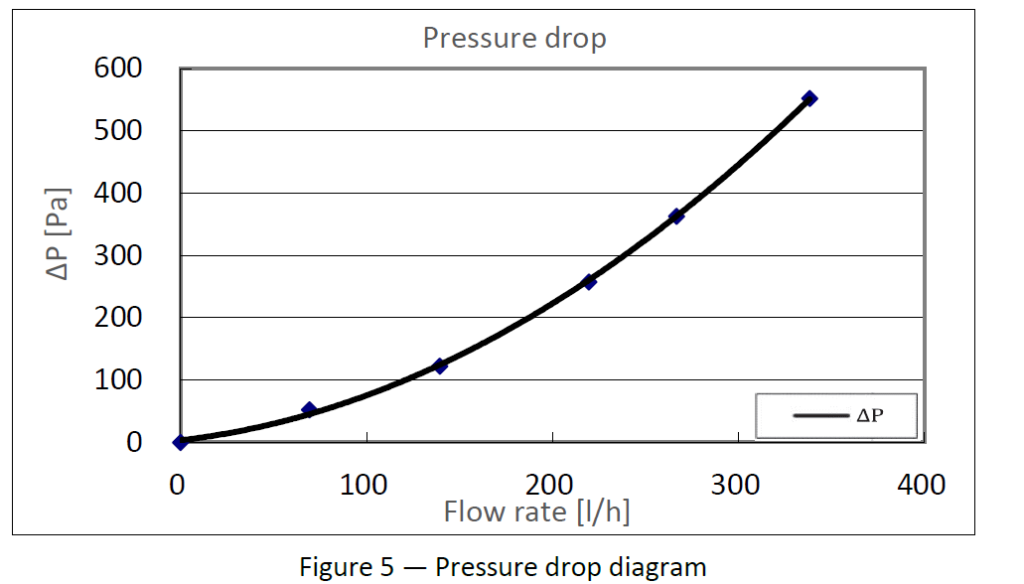
- Pressure-drop characteristics
Only by evaluating these parameters together can engineers estimate seasonal performance accurately and select the most suitable collector for a specific heat-pump application.